Sfd And Bmd Examples : Solved Example 20 Kn 40 Kn M V C 150 Knm 8 M 3 M 1 M A W Chegg Com. Example problem example problem 3 3. Shear force diagram (sfd) & bending moment diagram (bmd) form the basis for design of beams in general. Construct the sfd and bmd for 10 m span simply supported beam subjected to a system of loads as shown in figure 4.32. For windows xp start ansys by either using: Draw shear force and bending moment diagrams sfd and bmd for a simply supported beam subjected to three.
Learn vocabulary, terms and more with flashcards, games and other study tools. Draw sfd and bmd for the cantilever beam of 3 m long which carries a uniformly distributed load of 2 kn/m over a length of 2 m from the free end. > start a structural analysis, for example, will not need all the options available for a thermal, electromagnetic, or fluid dynamic analysis. Also locate points of contra flexure if any. Uniformly distributed load is that whose magnitude remains uniform throughout the length.
Why I Find The Shear Force Digram And Bending Moment Diagram Of A Beam Or Colume And What Is The Uses Of Sfd And Bmd In The Field Quora from qph.fs.quoracdn.net Problem 10 based on sfd and bmd video lecture from shear force & bending moment in beams chapter of strength of materials subject for all engineering student. Too obscure for me dear sntman. Construct the sfd and bmd for 10 m span simply supported beam subjected to a system of loads as shown in figure 4.32. 34 example problem example problem 3 3. 2)for uniformly distributed load load(udl) the degree of curve is 1st(linear) in sfd and 2nd(parabola) in bending moment diagram(bmd). A simply supported beam cannot have any translational displacements at. Use equilibrium conditions at all sections to. A simply supported beam is the most simple arrangement of the structure.
Join these points using curvatures depending upon the type of load as shown in figure 1.
34 example problem example problem 3 3. The beam is supported at each end, and the load is distributed along its length. Use equilibrium conditions at all sections to. You may receive emails, depending on your notification preferences. Sfd stands for shear force diagram. Draw sfd and bmd for the cantilever beam of 3 m long which carries a uniformly distributed load of 2 kn/m over a length of 2 m from the free end. Determine the absolute maximum bending moment and shear forces and mark them on sfd and bmd. This should be carried first before drawing sfd and. A simply supported beam cannot have any translational displacements at. Plotting sfd and bmd in one single graph for different conditions of the beams, such as cantilever with udl load, cantilever with the point loads etc. #sfd_bmd #sfd_bmd_continuous_beamhello friends,this video tutorial is on request of many people who wanted the sfd and bmd for continuous beam with udl and. Understanding these forces conceptually is the key to understanding their use in design and field. Also with the implementation of conjugate beam method or moment area method 4.
2)for uniformly distributed load load(udl) the degree of curve is 1st(linear) in sfd and 2nd(parabola) in bending moment diagram(bmd). Draw sfd and bmd for the single side overhanging beam subjected to loading as shown below. Find the internal torques at points b and c of the circular shaft subjected to three concentrated torques solution: However, this path will not be the same on all computers. Understanding these forces conceptually is the key to understanding their use in design and field.
Shear And Moment Diagram Wikipedia from upload.wikimedia.org Get the unknown sf and bm. Text of sfd and bmd. However, this path will not be the same on all computers. Determine the magnitude and direction of the reactions and the deflection and bending stress at the midpoint of the beam. Shear force diagram (sfd) & bending moment diagram (bmd) form the basis for design of beams in general. I have explained how to find them. 2)for uniformly distributed load load(udl) the degree of curve is 1st(linear) in sfd and 2nd(parabola) in bending moment diagram(bmd). Use equilibrium conditions at all sections to.
The diagram which shows the variation of bending moment along the length of the beam is called bending moment diagram (bmd).
Get the unknown sf and bm. Too obscure for me dear sntman. > start a structural analysis, for example, will not need all the options available for a thermal, electromagnetic, or fluid dynamic analysis. Below are the beam formulas and their respective sfd's and bmd's. This should be carried first before drawing sfd and. Understanding these forces conceptually is the key to understanding their use in design and field. Shear force diagram (sfd) & bending moment diagram (bmd) form the basis for design of beams in general. Uniformly distributed load is that whose magnitude remains uniform throughout the length. 63 sfd bmd 30kn 10kn 50kn parabola x = 1.5 m parabola 20knm 10knm point of contra flexure bmd cubic parabola 20knm. Example of a bending moment diagram. Axial force diagrams come additionally for column design. Determine the magnitude and direction of the reactions and the deflection and bending stress at the midpoint of the beam. Sfd and bmd plays an important role in the design of a beam based on strength criterion.
Shear force and bending moment diagrams internal forces in solids sign conventions shear forces are given 00 solid mechanics we can also demonstrate internal forces at a given section using above examples. Example of a bending moment diagram. Draw shear force and bending moment diagrams sfd and bmd for a simply supported beam subjected to three. Below are the beam formulas and their respective sfd's and bmd's. Find the internal torques at points b and c of the circular shaft subjected to three concentrated torques solution:
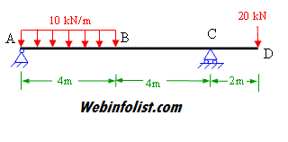
Civil Engineering Solved Examples For Shear Force And Bending Moment Diagram from civilengineer.webinfolist.com A simply supported beam is the most simple arrangement of the structure. Draw sfd and bmd for the single side overhanging beam subjected to loading as shown below. Problem 10 based on sfd and bmd video lecture from shear force & bending moment in beams chapter of strength of materials subject for all engineering student. The relationship between slope and maximum bending moment is inversely proportional because, for example in simply supported beams slope is maximum at supports and zero at midspan of a symmetrically loaded. The beam is supported at each end, and the load is distributed along its length. I have explained how to find them. Also locate points of contra flexure if any. Learn vocabulary, terms and more with flashcards, games and other study tools.
I mean bmd = bending moment diagram sfd = shear force diagram.
If 10k/ft load is acting on a beam whose length is 15ft. A simply supported beam cannot have any translational displacements at. Also locate points of contra flexure if any. 34 example problem example problem 3 3. 2)for uniformly distributed load load(udl) the degree of curve is 1st(linear) in sfd and 2nd(parabola) in bending moment diagram(bmd). I mean bmd = bending moment diagram sfd = shear force diagram. #sfd_bmd #sfd_bmd_continuous_beamhello friends,this video tutorial is on request of many people who wanted the sfd and bmd for continuous beam with udl and. What will be the variation in bmd for the diagram? This should be carried first before drawing sfd and. Get the unknown sf and bm. Find the internal torques at points b and c of the circular shaft subjected to three concentrated torques solution: Draw sfd and bmd for the single side overhanging beam subjected to loading as shown below. Draw sfd and bmd for the cantilever beam of 3 m long which carries a uniformly distributed load of 2 kn/m over a length of 2 m from the free end.
A simply supported beam is the most simple arrangement of the structure bmd sfd. Shear force and bending moment diagrams sfd & bmd.
Share :
Post a Comment
for "Sfd And Bmd Examples : Solved Example 20 Kn 40 Kn M V C 150 Knm 8 M 3 M 1 M A W Chegg Com"


Post a Comment for "Sfd And Bmd Examples : Solved Example 20 Kn 40 Kn M V C 150 Knm 8 M 3 M 1 M A W Chegg Com"